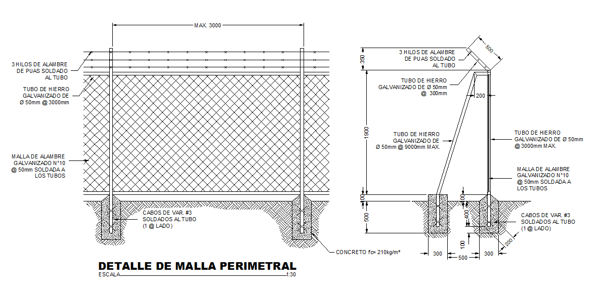
Steel Perimeter Fence Detail Drawing with Posts, Mesh, and Anchoring
Tags
Ratings & Reviews
Be the first to share your experience with this product. Your review helps others make better decisions!
Description
This steel perimeter fence detail drawing provides a complete structural view prepared in AutoCAD format, illustrating post placement, welded mesh, and anchoring details. The drawing shows galvanized iron tubes with a 50 mm diameter at specified spacing, concrete footing dimensions, and anchoring reinforcement bars. Barbed wire detailing, mesh welding, and top cap protection are clearly indicated. Dimensions for post height, mesh placement, and top wire spacing are labeled for accurate installation. The drawing also highlights the integration of concrete footing with the surrounding soil, ensuring stability and structural integrity of the fence system. All material specifications, welding points, and post anchoring details are included to support precise field execution.
This steel detail design is useful for architects, civil engineers, builders, and site planners involved in residential, commercial, and industrial projects. The AutoCAD DWG file allows easy editing, scaling, and coordination with architectural or site layouts using AutoCAD, Revit, or SketchUp. The clear sectional and plan views provide a visual guide for proper mesh installation, anchoring sequence, and bar spacing, ensuring the fence meets safety and structural standards. This drawing helps professionals plan, estimate, and execute fence construction efficiently, reducing errors and ensuring durability. It is a valuable CAD resource available through a Cadbull subscription.

Uploaded by:
john kelly
Tags
Ratings & Reviews
Be the first to share your experience with this product. Your review helps others make better decisions!