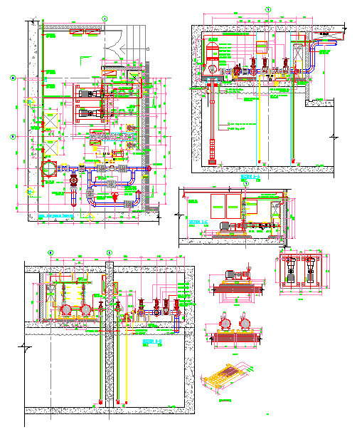
Pumping Room DWG with Equipment Layout, Pipes, and Structural Details
Tags
Ratings & Reviews
Be the first to share your experience with this product. Your review helps others make better decisions!
Description
This Pumping Room DWG provides a detailed AutoCAD layout of a pumping station, including pumps, piping, valves, and structural components. The drawing shows equipment placement, fluid flow paths, and connection points, enabling architects, civil engineers, and builders to plan precise installation of pumps and associated systems. All components, including inlets, outlets, tanks, and support structures, are clearly labeled to ensure accurate design, fabrication, and operational efficiency. The DWG covers sectional views, elevations, and detailed connections for proper integration with building infrastructure.
The CAD file is compatible with AutoCAD, Revit, 3D Max, and SketchUp, allowing seamless integration into 2D and 3D models for mechanical, electrical, and plumbing coordination. It highlights valve locations, pipe routes, and pump alignment for optimal performance and maintenance access. Subscribing to cadbull.com provides access to high-quality DWG files like this Pumping Room layout, saving drafting time while ensuring precise planning. This DWG ensures clarity in equipment placement, piping layout, and structural supports, making it an essential resource for professional pump station design and construction.

Uploaded by:
Jafania Waxy
Tags
Ratings & Reviews
Be the first to share your experience with this product. Your review helps others make better decisions!