Cantilever Bridge Design Drawing with Section Elevation and Dimensions
Tags
Ratings & Reviews
Be the first to share your experience with this product. Your review helps others make better decisions!
Description
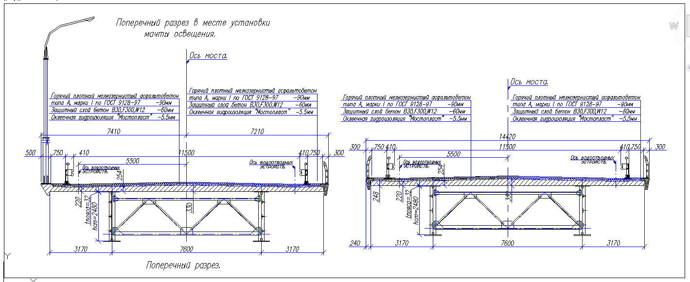
This cantilever bridge design drawing AutoCAD DWG file presents a detailed structural layout with clear sectional views and elevation details. The drawing illustrates the cantilever bridge deck arrangement, support frames, beam connections, and measured span lengths. It includes dimensioned deck width, cantilever arm lengths, pier spacing, and structural depth details as shown in the drawing. The sectional cut highlights layered deck construction, support brackets, and load transfer elements, making it useful for understanding cantilever bridge behaviour. Precise measurements such as span lengths, offsets, and support distances are clearly marked for technical reference and design coordination.
The cantilever bridge design drawing is suitable for academic study and professional planning. It helps architects and civil engineers analyse bridge geometry, structural alignment, and construction detailing. Builders and infrastructure designers can use this drawing to study support placement, deck projection, and cantilever balance principles. The AutoCAD DWG format allows easy modification, scaling, and integration into larger infrastructure projects. This drawing is ideal for learning structural detailing, preparing bridge proposals, and referencing standard cantilever bridge design practices with accurate measurements and clear annotations.

Uploaded by:
Harriet Burrows
Tags
Ratings & Reviews
Be the first to share your experience with this product. Your review helps others make better decisions!