Drainage Detail DWG Design 0.60x1.20 Concrete Layout Section
Tags
Ratings & Reviews
Be the first to share your experience with this product. Your review helps others make better decisions!
Description
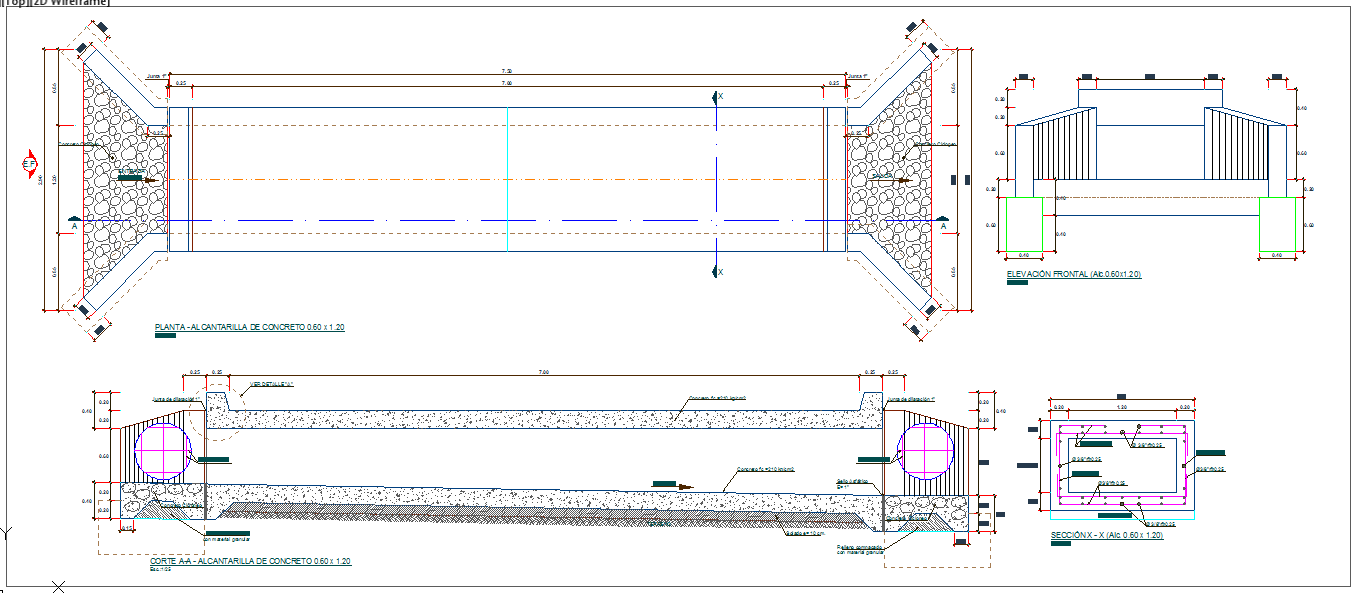
This Drainage Detail DWG file provides a complete technical layout of a 0.60 x 1.20 m concrete drainage system, designed for efficient water management. The drawing includes detailed top plan views, cross-section X-X, frontal elevation, and sectional cuts to illustrate the complete structural design. Dimensions, conduit positions, and reinforcement details are clearly marked, allowing architects, civil engineers, and construction professionals to implement precise construction workflows. The plan highlights the concrete channel with side slopes, inlet and outlet arrangements, and stone fill layers for proper drainage.
The sectional view of the drainage system includes a detailed depiction of the culvert structure, pipe placement, and reinforcement arrangement. Users can see exact measurements such as 0.60 m width, 1.20 m height, and the full 7 m length of the drainage channel. The drawing is ideal for AutoCAD, Revit, 3D Max, and SketchUp users for both planning and execution. This DWG file ensures that engineers, builders, and interior designers have all technical details at their fingertips for accurate project execution. Download this Drainage Detail DWG for precise construction planning and professional engineering use.

Uploaded by:
Harriet Burrows
Tags
Ratings & Reviews
Be the first to share your experience with this product. Your review helps others make better decisions!