Chilled Water Pump Room Layout Plan with Piping and Foundation Details
Tags
Ratings & Reviews
Be the first to share your experience with this product. Your review helps others make better decisions!
Description
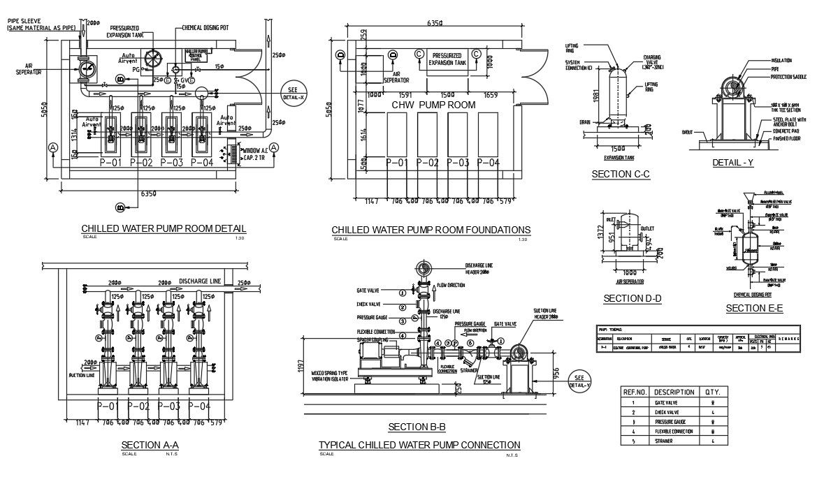
This AutoCAD DWG drawing provides a complete chilled water pump room layout with detailed mechanical and piping arrangements for HVAC systems. The file includes pump room planning with overall dimensions of approximately 6350mm length and 5050mm width, four pump units P01 to P04, suction and discharge lines of 250mm diameter, expansion tank connections, air separator, and chemical dosing pot arrangement. The layout shows clear spacing between equipment, foundation levels, and access paths for maintenance. It also includes sectional views, valve locations, pressure gauges, flexible connectors, and insulation details for accurate system installation. The chilled water pump room foundation drawing also covers structural and service coordination with RCC base dimensions, vibration isolators, anchor bolt positioning, and equipment pedestal heights. The AutoCAD chilled water pump room piping detail presents section A A, B B, C C, D D, and E E views with precise measurements, flange connections, drain points, and vent arrangements. This HVAC pump room mechanical layout supports engineers and consultants in preparing construction drawings, shop drawings, and execution plans for commercial buildings, hospitals, malls, and industrial facilities.
File Type:
Autocad
Category::
Structure
Sub Category::
Section Plan CAD Blocks & DWG Drawing Models
type:
Gold
Uploaded by:
Mehul Patel
Tags
Ratings & Reviews
Be the first to share your experience with this product. Your review helps others make better decisions!