Cantilever Beam Section DWG with 3500 mm and 3000 mm Reinforcement
Ratings & Reviews
Be the first to share your experience with this product. Your review helps others make better decisions!
Description
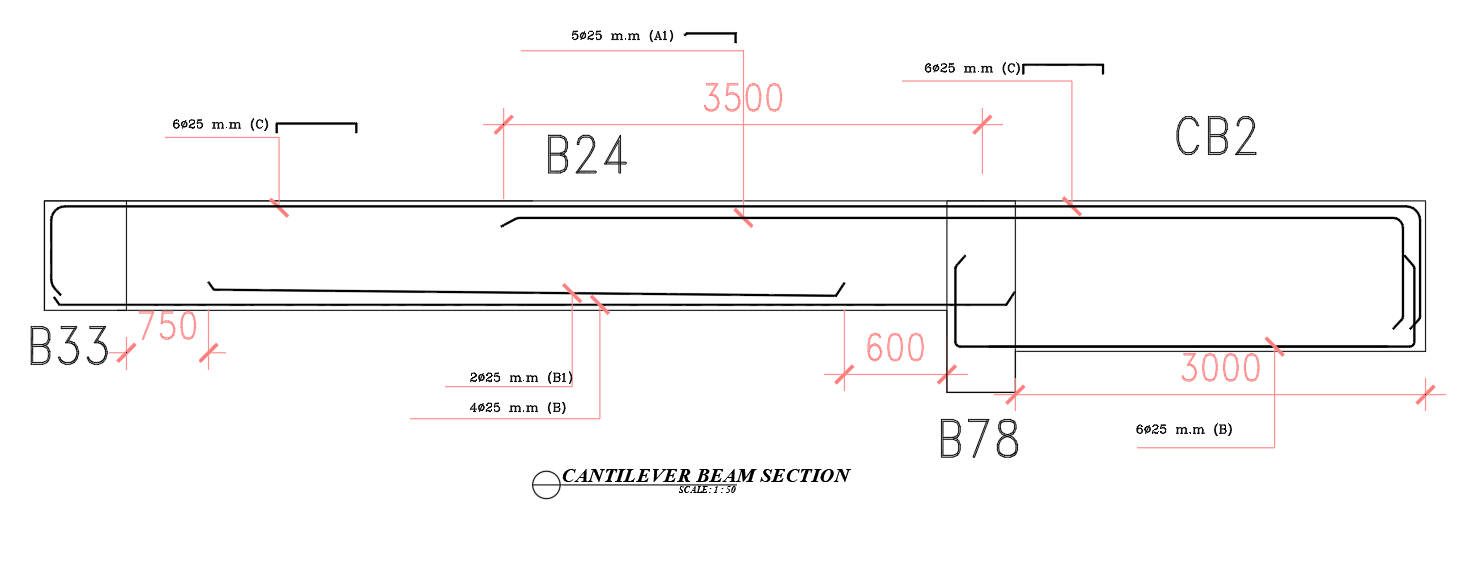
This AutoCAD DWG file provides a fully detailed cantilever beam section, showcasing precise measurements, reinforcement layout, and span dimensions required for structural engineering work. The drawing illustrates beam identifiers including B33, B24, B78, and CB2, each represented with accurate geometry and reinforcement bending profiles. The primary cantilever section displays a 3500 mm central span, paired with a 3000 mm continuation length and shorter extensions such as 750 mm and 600 mm, ensuring a clear understanding of load transfer and beam performance. The included top and bottom reinforcement bars are drawn with correct anchorage and development lengths, supporting safe and efficient structural execution.
The plan highlights multiple dimension sets such as 6825 mm (C), 5025 mm (A1), 4025 mm (B), and 2025 mm (B1), allowing users to interpret all projection lengths from the fixed support outward. The neatly drafted linework clarifies where bending moments shift along the cantilever, while the section marking identifies the precise reinforcement distribution along the beam’s tension and compression zones. Ideal for architects, civil engineers, and structural professionals, this DWG file helps streamline construction planning, reinforcement detailing, and site execution by providing a complete, accurate, and easy-to-understand cantilever beam layout.
Tags
Uploaded by:
manveen
kaur
Ratings & Reviews
Be the first to share your experience with this product. Your review helps others make better decisions!