Column Splice Reinforcement Detail After Slab in DWG Drawing
Tags
Ratings & Reviews
Be the first to share your experience with this product. Your review helps others make better decisions!
Description
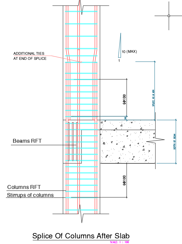
This AutoCAD DWG drawing provides a clear and detailed column splice reinforcement layout after slab level, illustrating how vertical bars, stirrup spacing, and additional ties are arranged for proper structural continuity. The drawing shows the splice length of 900 mm, the positioning of column RFT, and the integration of beam reinforcement intersecting at slab level. It includes essential details such as the 10 mm maximum spacing for ties at the end of splice, the depth of beam, and the exact alignment of reinforcement passing through the slab. These details help ensure correct bar anchorage, load transfer, and structural stability at the critical junction between slab and column.
The drawing further highlights the arrangement of stirrups around column bars, the beam RFT zone, and the accurate placement of ties in both vertical and horizontal directions. Every measurement is marked precisely, supporting engineers and designers in following accurate reinforcement guidelines during construction. This DWG file is highly useful for architects, structural engineers, and contractors involved in high-rise, residential, and commercial building projects where safe and compliant column splicing is required. The detail ensures correct implementation on site and supports reliable performance of reinforced concrete structural members.
Uploaded by:
manveen kaur
Tags
Ratings & Reviews
Be the first to share your experience with this product. Your review helps others make better decisions!