Electrical Diagram Spare Connection with Underground Cables DWG File
Tags
Ratings & Reviews
Be the first to share your experience with this product. Your review helps others make better decisions!
Description
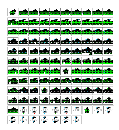
This detailed CAD drawing presents a complete electrical spare connection diagram featuring underground cable routing, terminal arrangements, and connection points represented across multiple symbol sets. Each block illustrates the coordinated layout of cable joints, spare line connections, feeder routes, switching symbols, and protective device markers. The underground cables are shown using clear line types and directional indicators that help identify how circuits branch and merge within the system. This sheet contains multiple repeated diagrams to represent different spare configurations, ensuring flexibility for various electrical planning needs in commercial, industrial, and infrastructure projects.
The drawing also includes bottom-row connection symbols showing feeder terminations, spare socket links, and directional flow marks that support accurate electrical coordination during design and installation. These diagrams help electrical engineers understand cable grouping, routing patterns, and spare allocation used for system expansion or future upgrades. The organized grid layout supports quick referencing and standardization across larger electrical networks. This DWG file is especially useful for drafting underground cable plans, preparing connection schedules, and visualizing spare circuits in structured electrical systems for engineering teams.
Uploaded by:
Priyanka Patel
Tags
Ratings & Reviews
Be the first to share your experience with this product. Your review helps others make better decisions!