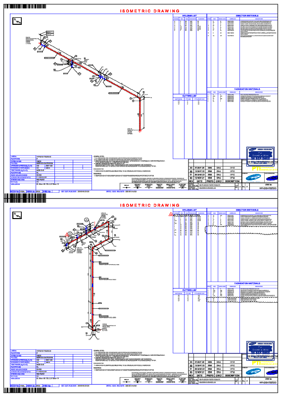
Isometric Piping DWG with Weld List, Cut List, and Full Line Routing

Ratings & Reviews
Be the first to share your experience with this product. Your review helps others make better decisions!
Description
This AutoCAD DWG file presents two complete piping isometric drawings, showing full line routing, component placement, and fabrication details essential for industrial piping design and construction. The drawings include pipe sizes, directional changes, slope indications, insulation notes, and elevation markers, providing precise guidance for installation. Each isometric view displays equipment nozzles, reducers, tees, elbows, valves, flanges, supports, and tagged components for easy identification. The file also includes a detailed weld list, cutting list, and support list on page 1 of the sheet, ensuring fabricators have the required information for spool preparation and field assembly. Weld numbers, joint types, and lengths are clearly documented for QA/QC verification.
Additional sections outline important fabrication notes, material specifications, and NDT requirements, supporting compliance with project standards. Each isometric drawing highlights spool boundaries, flow direction, and pipe routing distances, ensuring accurate pipe fit-up during erection. Elevation differences and anchor points help engineers understand piping stresses and support requirements. This DWG is ideal for piping engineers, fabrication contractors, MEP consultants, and industrial plant designers who require a reliable and accurate piping isometric DWG for manufacturing and installation workflows, complemented by architectural façade reference material such as curtain elevation design drawings prepared in AutoCAD DWG format for presentation and coordination use.
File Type:
DWG
File Size:
174 KB
Category::
Dwg Cad Blocks
Sub Category::
Autocad Plumbing Fixture Blocks
type:
Gold
Tags
Uploaded by:
Neha
mishra
Ratings & Reviews
Be the first to share your experience with this product. Your review helps others make better decisions!