Septic Tank Design Detail Drawing With Chamber Section and Levels
Tags
Ratings & Reviews
Be the first to share your experience with this product. Your review helps others make better decisions!
Description
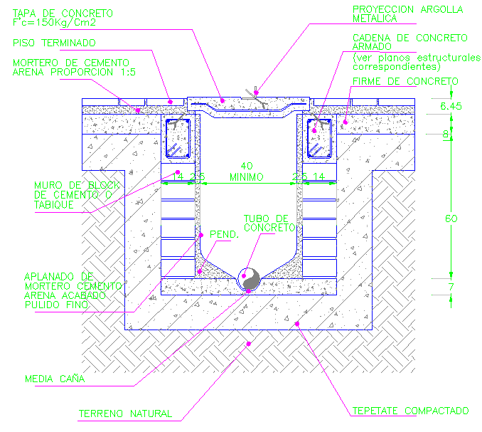
This septic tank design detail drawing presents a clear sectional construction layout of a concrete septic tank system with internal chambers and outlet connections. The AutoCAD drawing illustrates reinforced concrete walls, base slab, top concrete cover, and internal partition with accurate millimeter measurements. Key dimensions such as minimum internal width of 40 cm, overall depth around 60 cm, and pipe slope indication are clearly marked. The drawing also shows concrete pipe inlet and outlet positioning, bottom half-round channel formation, compacted soil bedding, and natural ground levels to support correct wastewater flow and sediment settlement.
The septic tank design drawing is suitable for architects, civil engineers, and builders who require precise construction documentation for onsite wastewater treatment systems. Sectional details explain reinforced concrete elements, masonry block walls, plastered internal surfaces, and concrete finishing layers. Level markings, slope direction, and structural thickness are clearly defined in mm scale to ensure proper execution and durability. This AutoCAD DWG file can be directly used in AutoCAD, 3d Max, Revit, and Google SketchUp for professional detailing and construction drawings, making it a reliable reference for septic tank planning and installation.

Uploaded by:
Harriet Burrows
Tags
Ratings & Reviews
Be the first to share your experience with this product. Your review helps others make better decisions!