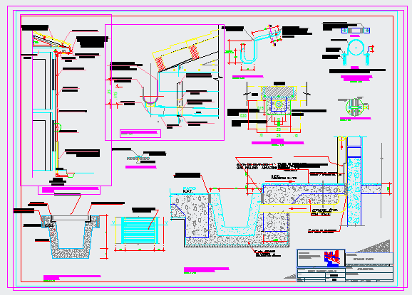
Typical Rain Water System Layout Drawing with Plan Section Elevation
Ratings & Reviews
Be the first to share your experience with this product. Your review helps others make better decisions!
Description
This AutoCAD file provides a comprehensive typical rainwater system detail with plan, sectional, and elevation views. It includes pipe diameters, 100mm to 150mm gutter layouts, downpipe connections, roof drainage slopes, and catchment areas, showing measurements and materials for proper installation. Architects, civil engineers, and interior designers can visualize the full drainage system, including sectional details of pipe junctions, rainwater inlets, and overflow mechanisms. The drawing also features elevation detailing to ensure correct slope and flow, with all dimensions clearly labeled for precise implementation. Suitable for AutoCAD, 3D Max, Revit, and SketchUp users, this DWG file helps in planning efficient water drainage in residential and commercial projects, providing clear guidance for contractors and builders. Perfect for designing sustainable water management systems with detailed construction clarity.
File Type:
3d max
File Size:
4.2 MB
Category::
Structure
Sub Category::
Section Plan CAD Blocks & DWG Drawing Models
type:
Gold
Tags
Uploaded by:
zalak
prajapati
Ratings & Reviews
Be the first to share your experience with this product. Your review helps others make better decisions!