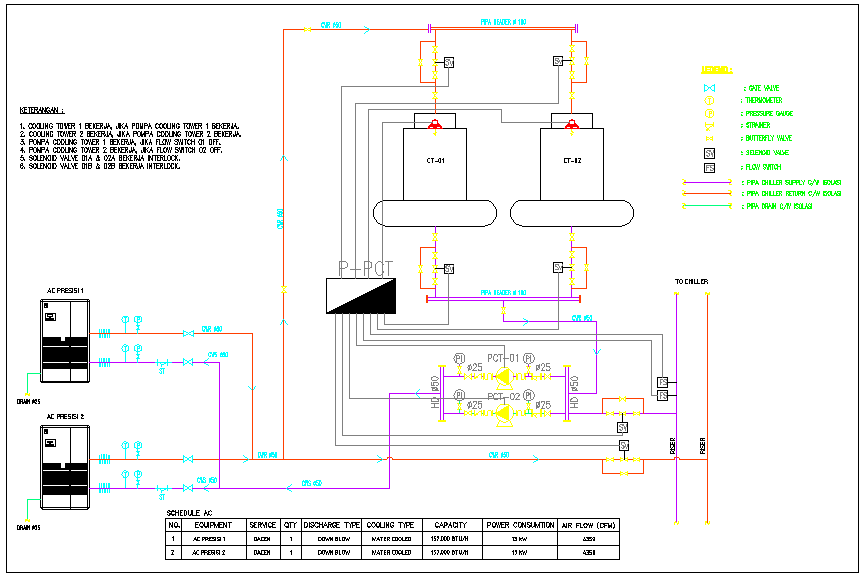
AC Cooling Tower Schematic Diagram with Pipe Valve System Details
Tags
Ratings & Reviews
Be the first to share your experience with this product. Your review helps others make better decisions!
Description
This AC and Cooling Tower Schematic Diagram DWG file provides a detailed mechanical layout of cooling systems used in buildings and industrial setups. The drawing includes complete pipe routing, valve placement, and system connections between air conditioning units and cooling towers. Each component is clearly illustrated with accurate dimensions, showing flow direction, control points, and integration of cooling systems. The schematic representation helps in understanding the relationship between AC systems and cooling tower operations, ensuring proper installation and efficient performance.

Uploaded by:
Liam White
Tags
Ratings & Reviews
Be the first to share your experience with this product. Your review helps others make better decisions!