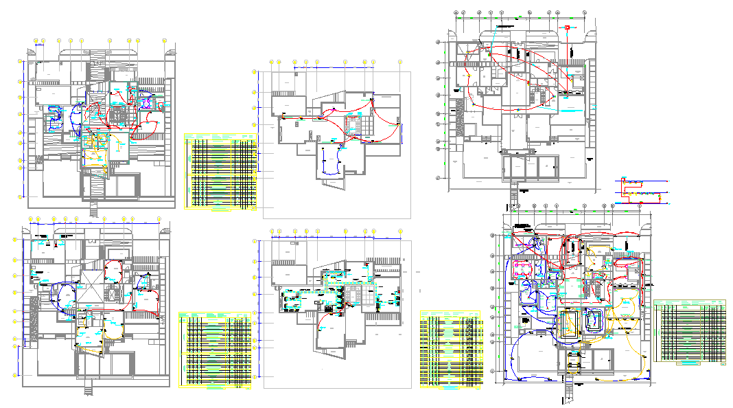
First Floor Electrical Power Layout Plan With Circuit Routing Details
Tags
Ratings & Reviews
Be the first to share your experience with this product. Your review helps others make better decisions!
Description
This AutoCAD drawing shows a first-floor electrical power layout plan with complete internal power distribution details. The drawing clearly illustrates socket point locations, power outlet positioning, switch boards, circuit routing paths, and panel connectivity arranged across the first floor spaces. Color-coded wiring paths indicate different power circuits for rooms, service areas, and common circulation zones, helping users understand load separation and functional zoning. Grid references, wall outlines, and room boundaries are accurately coordinated to support the precise placement of electrical components. The layout reflects standard residential planning practice with balanced circuit distribution and logical routing for easy coordination with architectural drawings.
The first-floor power layout drawing is useful for architects, civil engineers, interior designers, and electrical consultants preparing coordinated building documentation. The plan supports design development and construction drawings by providing readable circuit paths, reference tables, and legend information linked to the layout. Measurement alignment with structural grids and room proportions helps ensure proper execution on site. This drawing can be directly used for detailing, checking electrical planning accuracy, and integrating power layouts with lighting and service drawings during project execution.

Uploaded by:
Fernando Zapata
Tags
Ratings & Reviews
Be the first to share your experience with this product. Your review helps others make better decisions!