Septic Tank Designs Drawing with Chambers Layout Size Levels
Tags
Ratings & Reviews
Be the first to share your experience with this product. Your review helps others make better decisions!
Description
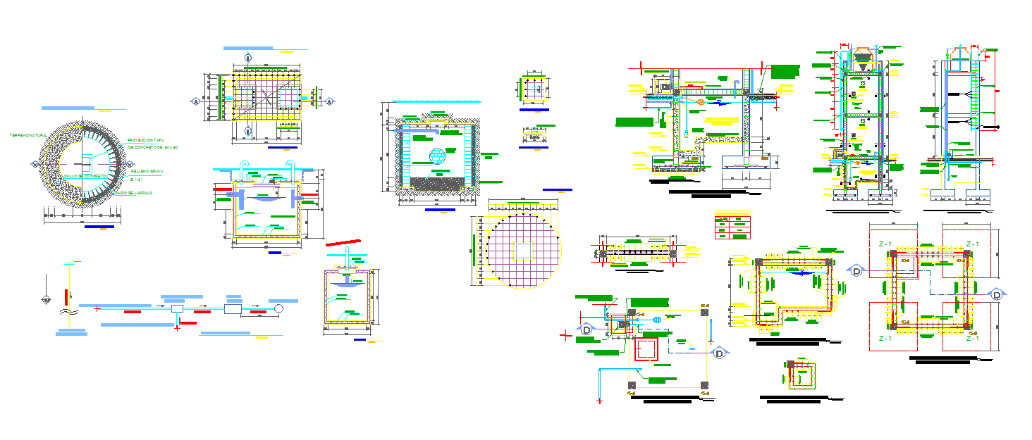
This septic tank design AutoCAD drawing presents a clear and practical layout used for residential and small building sanitation planning. The drawing includes a detailed plan view showing inlet and outlet pipe positions, internal partition wall, sludge settling zone, and liquid chamber arrangement. Standard dimensions are clearly marked in millimetres with overall length, width, depth, wall thickness, and base slab size. The section detail explains liquid level, freeboard, scum layer, sludge zone, and ventilation pipe position, making it suitable for civil engineers and architects preparing plumbing and drainage layouts.
The septic tank design detail also covers construction information such as RCC wall thickness, base slab thickness, manhole cover location, and inspection chamber connectivity. Pipe diameters, slope direction, and chamber spacing are properly indicated for accurate execution on site.

Uploaded by:
john kelly
Tags
Ratings & Reviews
Be the first to share your experience with this product. Your review helps others make better decisions!