Structure Detail Drawing With Concrete Anchors And Pipe Fixing
Tags
Ratings & Reviews
Be the first to share your experience with this product. Your review helps others make better decisions!
Description
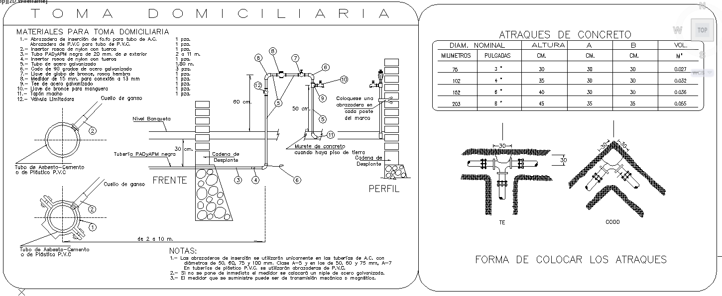
This structure detail drawing presents a clear construction level detailing prepared in AutoCAD format, focusing on concrete anchor blocks, pipe fixing, and installation layout. The drawing includes front, profile, and sectional views showing domestic connection arrangements, pipe routing, clamp positions, and concrete support details. Nominal diameters, pipe sizes in millimetres and inches, concrete block dimensions, and installation heights are clearly defined to support accurate execution. Tables specify anchor sizes, concrete volume, and dimensional variations for different pipe diameters, ensuring clarity in selection and construction planning.
The structural detail design also illustrates correct placement methods for concrete anchors, elbow joints, and tee connections within masonry and ground conditions. Notes and callouts explain the fixing sequence, spacing, and support requirements to maintain structural stability. Material identification, pipe alignment, and installation tolerances are clearly annotated for practical on-site application. This structure detail AutoCAD drawing is suitable for architects, civil engineers, and construction professionals who require precise technical detailing for pipe support systems and concrete anchoring within building infrastructure projects.

Uploaded by:
Harriet Burrows
Tags
Ratings & Reviews
Be the first to share your experience with this product. Your review helps others make better decisions!