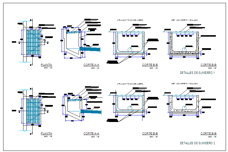
Drainage Road Design Drawing with Catch Pit Sections and Dimensions
Tags
Ratings & Reviews
Be the first to share your experience with this product. Your review helps others make better decisions!
Description
This AutoCAD DWG file provides a detailed drainage road design drawing with clearly defined layouts, sections, and construction details required for surface water management. The drawing includes plan views of drainage alignment along the road, showing catch pits, sumidero details, and connection points integrated with the pavement structure. Section A and Section B illustrate the internal build-up of drainage chambers, reinforced concrete walls, base slab thickness, and inlet and outlet pipe positioning with precise measurements. Steel reinforcement arrangement, concrete grades, and finishing layers are indicated to support durability and load resistance under road traffic conditions. Dimensional annotations guide correct excavation depth, chamber width, and cover placement for accurate site execution. The drawing helps coordinate civil and structural works by explaining how drainage elements connect with the road profile and surrounding ground levels. Drafted to scale with clear labels, this drainage road design DWG is suitable for urban roads, access roads, and infrastructure projects. Architects, civil engineers, and builders can use this file for design development, approval drawings, and construction planning using AutoCAD-compatible workflows.

Uploaded by:
Jafania Waxy
Tags
Ratings & Reviews
Be the first to share your experience with this product. Your review helps others make better decisions!