Industrial Layout Plan DWG with Gas Oil Line and Machine Setup
Tags
Ratings & Reviews
Be the first to share your experience with this product. Your review helps others make better decisions!
Description
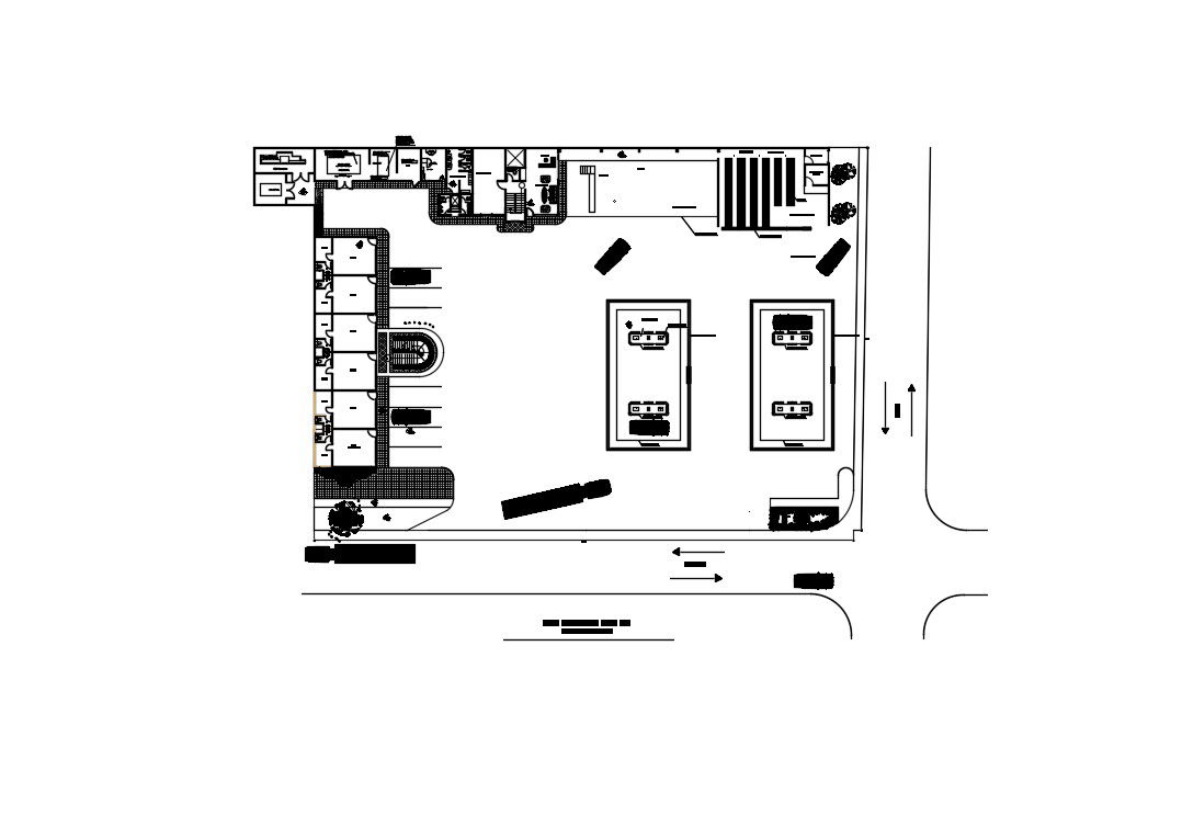
This Industrial Layout Plan DWG File provides a complete set of technical drawings prepared in AutoCAD format for factory and production facility planning. The layout includes detailed positioning of machinery units, work zones, storage areas, service rooms, and circulation pathways. It also presents gas line routing, oil pipeline diagrams, utility connections, safety clearances, and equipment foundation layouts. The drawing shows standard dimensions such as machine spacing of approximately 1500 mm, service corridor width of 1800 mm, pipeline diameter of 100 mm, maintenance clearance of 1200 mm, and loading bay width of 4000 mm for efficient operations and safety compliance.
This AutoCAD industrial layout drawing is suitable for industrial engineers, civil engineers, plant managers, and project consultants who require accurate working drawings for plant setup and expansion projects. The file supports AutoCAD, Revit, 3ds Max, and SketchUp software for easy editing and customization. It can be used for manufacturing units, workshops, processing plants, and utility facilities. With organized layers, accurate scaling, and clear system annotations, this drawing improves workflow planning, reduces installation errors, and enhances operational efficiency. Subscribers can download this professional DWG file to save drafting time, improve documentation quality, and ensure reliable industrial infrastructure planning.
Uploaded by:
Priyanka Patel
Tags
Ratings & Reviews
Be the first to share your experience with this product. Your review helps others make better decisions!