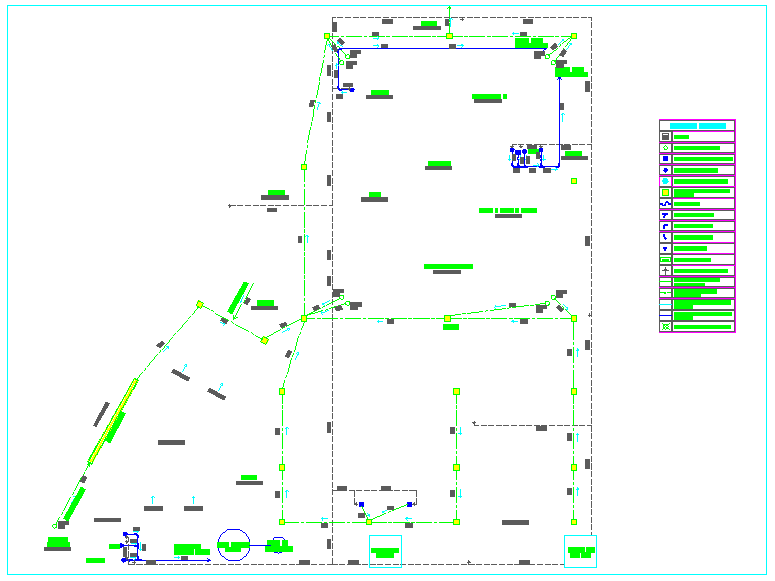
Hydraulic Line Layout Design with Detailed Measurements and Symbols
Tags
Ratings & Reviews
Be the first to share your experience with this product. Your review helps others make better decisions!
Description
This hydraulic line layout design, presented in AutoCAD DWG format, includes a comprehensive schematic for fluid distribution systems. The layout features accurate placement of pipes, valves, and connectors, ensuring seamless integration into any architectural or engineering project. With precise measurements and a clear graphical representation of components, this drawing aids in the creation of efficient hydraulic systems for commercial or residential constructions. Essential symbols for pipes, valves, and system components are detailed, providing clarity for engineers and architects. This AutoCAD file is a valuable resource for civil engineers, architects, and other professionals involved in hydraulic design projects, offering high-quality, editable schematics suitable for advanced design and construction work. Available for immediate use in your projects!

Uploaded by:
Liam White
Tags
Ratings & Reviews
Be the first to share your experience with this product. Your review helps others make better decisions!