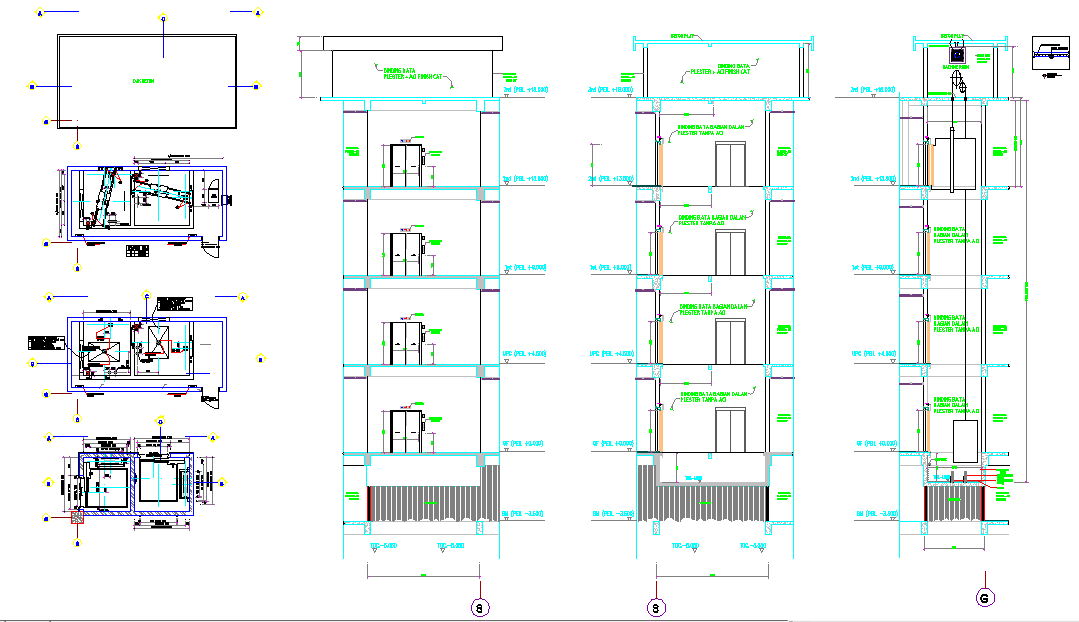
Bridge Lift Structure Elevation Plan with Gate Mechanism Design
Tags
Ratings & Reviews
Be the first to share your experience with this product. Your review helps others make better decisions!
Description
This AutoCAD drawing presents a detailed bridge lift structure elevation plan focusing on the complete lift design system used in infrastructure and industrial projects. The drawing clearly illustrates the vertical elevation of the lift, structural framing, guide rails, base supports, and alignment with the bridge structure. It includes a precise representation of lift shaft positioning, platform levels, support columns, and load-bearing elements required for safe vertical movement. The layout is created with professional CAD layering, line weights, and annotations suitable for construction-level reference.
The drawing also provides technical details of the lift gate mechanism, showing springs, locking components, gate alignment, and motion-control parts integrated into the lift structure. Mechanical connections, fixing points, and operational clearances are illustrated to support accurate fabrication and installation. This lift elevation plan is ideal for architects, civil engineers, and builders involved in bridge infrastructure, transport facilities, and heavy structure projects who require reliable AutoCAD-based design documentation.

Uploaded by:
Harriet Burrows
Tags
Ratings & Reviews
Be the first to share your experience with this product. Your review helps others make better decisions!