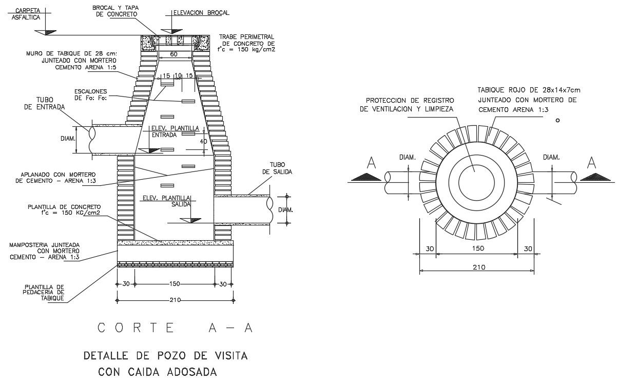
Sewage Chamber Design Drawing with Manhole and Tank Details.
Tags
Ratings & Reviews
Be the first to share your experience with this product. Your review helps others make better decisions!
Description
This sewage chamber design drawing provides a detailed AutoCAD representation of a sewer inspection chamber with complete construction and dimensional information. The drawing illustrates the vertical section and plan view of the sewage chamber, showing manhole cover placement, concrete frame details, and chamber wall construction. It includes masonry wall thickness, internal plaster finish, concrete base slab, and a step iron arrangement for safe access. Clear annotations define inlet and outlet pipe connections with diameter markings, elevation levels, and slope direction for smooth sewage flow. The chamber cover, frame seating, and peripheral concrete beam details are also represented to support structural stability at ground level.
Uploaded by:
Priyanka Patel
Tags
Ratings & Reviews
Be the first to share your experience with this product. Your review helps others make better decisions!