Manometer Instrument Detailed Plan Elevation and Section AutoCAD
Tags
Ratings & Reviews
Be the first to share your experience with this product. Your review helps others make better decisions!
Description
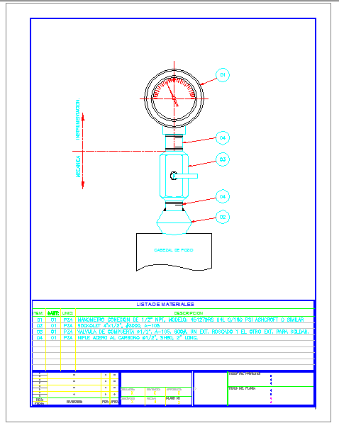
This AutoCAD DWG file provides detailed drawings of a manometer, an instrument used to measure pressure acting on a fluid column. The drawing includes plan, elevation, and sectional views showing the U-shaped tube, fluid column, and pressure connection points. Architects, civil engineers, and mechanical designers can use this file to study the pressure measurement system, alignment, and installation requirements for building or mechanical projects.
The DWG also includes detailed labeling of components such as valves, connectors, and measurement points for accurate assembly and functional understanding. Builders and engineers can refer to these details to ensure precise installation, fluid column calibration, and pressure reading accuracy. This professional drawing serves as a reference for planning, technical detailing, and execution of manometer setups in residential, commercial, or industrial applications using AutoCAD.
Uploaded by:
viddhi chajjed
Tags
Ratings & Reviews
Be the first to share your experience with this product. Your review helps others make better decisions!